

How Does Supply Pressure Fluctuation Affect a Pneumatic Diaphragm Actuator’s Performance
2026-06-29
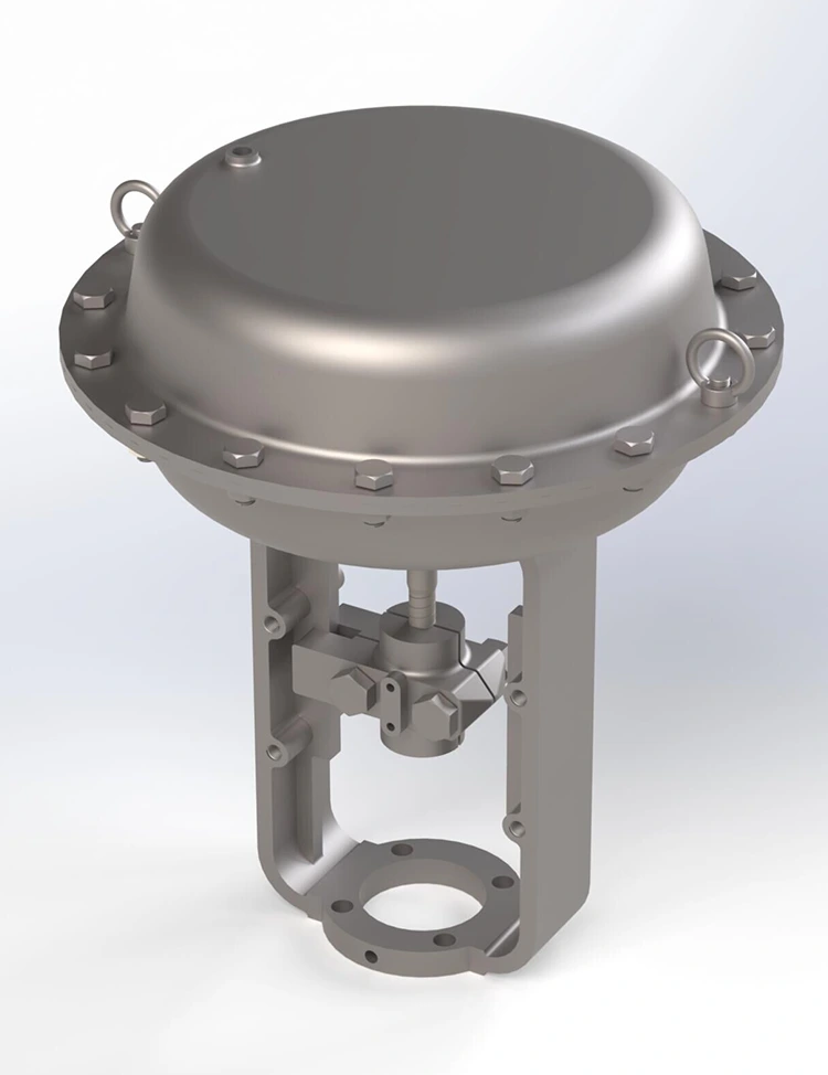
In industrial control systems, the Pneumatic Diaphragm Actuator is widely trusted for its simplicity, reliability, and linear response. However, one variable that consistently challenges its accuracy is supply pressure instability. Even modest variations in instrument air pressure can degrade positioning precision, accelerate component wear, and compromise process safety. At Lozose, we have engineered our Pneumatic Diaphragm Actuators to mitigate these effects—but understanding the underlying physics remains essential for any maintenance or engineering team.
The Direct Impact of Pressure Fluctuation
Supply pressure (typically 3–15 psi or 4–20 mA equivalent) acts as the actuator’s “fuel.” When this pressure deviates from its setpoint, three performance parameters suffer immediately:
| Performance Metric | Effect of Pressure Drop (–10%) | Effect of Pressure Surge (+15%) |
|---|---|---|
| Stroke Accuracy | Under-travel (up to 8% position error) | Over-travel with oscillation |
| Response Speed | Slower stroking time (delay > 0.5s) | Faster but erratic motion |
| Seat Load (Shut-off) | Insufficient force → leakage risk | Excessive seat wear → shortened cycle life |
| Air Consumption | Slight decrease | Significant increase (wasted energy) |
| Diaphragm Lifespan | Minimal effect | Accelerated fatigue (rupture risk) |
Beyond these metrics, a fluctuating supply introduces hysteresis and deadband widening—two non-linearities that confuse positioners and force controllers into constant overcorrection, creating a destructive oscillation loop.
Why Does This Happen?
A Pneumatic Diaphragm Actuator operates on a force-balance principle:
Output Force = (Supply Pressure – Spring Force) × Effective Diaphragm Area.
When supply pressure changes, the net force changes proportionally. If the spring rate is fixed, the stem position shifts unless the positioner actively compensates. In practice:
-
Low pressure → insufficient thrust to overcome process flow forces → valve plug lifts off seat prematurely.
-
High pressure → diaphragm stretches beyond design limits → permanent deformation and reduced effective area over time.
Lozose recommends installing a precision filter-regulator-lubricator (FRL) within 5 feet of every actuator inlet, and using a volume booster for long pneumatic lines to dampen rapid transients.
3 FAQ Common Questions About Pneumatic Diaphragm Actuators
Q1: Can a digital positioner completely eliminate the effect of supply pressure fluctuation on a Pneumatic Diaphragm Actuator?
A: Not completely, but it can reduce the error significantly. A digital positioner with built-in pressure sensors uses a feed-forward algorithm to adjust the output nozzle pressure in real time, compensating for up to ±20% supply variation. However, if the supply drops below the minimum required bench set range, even the best positioner cannot create force—it physically lacks air mass. For critical loops, Lozose recommends pairing our actuators with a dedicated pneumatic relay and a secondary accumulator tank to guarantee stable inlet pressure during momentary plant-wide air dips.
Q2: How often should I recalibrate my Pneumatic Diaphragm Actuator if my plant experiences frequent pressure swings?
A: In stable environments, annual calibration suffices. But with frequent swings (>5 events per hour), we advise quarterly full-stroke tests plus monthly static pressure checks. More importantly, monitor the actuator’s travel deviation at 50% signal—if it exceeds ±2.5% of span, recalibrate immediately. Lozose offers a predictive maintenance dashboard that logs supply pressure history and stroke response, alerting your DCS when deviation trends exceed user-defined thresholds, enabling condition-based rather than calendar-based scheduling.
Q3: What is the maximum allowable supply pressure variation before a Pneumatic Diaphragm Actuator risks permanent damage?
A: Most industrial-grade actuators tolerate ±10% of nominal pressure without mechanical damage, but performance degrades beyond ±5%. The absolute maximum is usually 150% of rated max pressure (e.g., 30 psi for a 20-psi max unit)—exceeding this stretches the diaphragm fabric reinforcement, causing micro-tears. Once micro-tears appear, fatigue life drops by 70% within 2000 cycles. Lozose actuators incorporate an integral overpressure relief vent and a color-indicating stem that visually signals diaphragm over-stretch, giving operators an immediate on-site warning before catastrophic failure occurs.
Best Practices to Stabilize Performance
| Action | Frequency | Expected Benefit |
|---|---|---|
| Install dedicated FRL with gauge | At installation | Reduces ripple to < ±0.5 psi |
| Check supply header pressure trend | Daily (via SCADA) | Detects compressor degradation early |
| Inspect diaphragm for cracking | Every 6 months | Prevents sudden loss of thrust |
| Test stroke time at min/max signal | Quarterly | Quantifies dynamic response shift |
| Replace filter element | Every 3 months | Maintains flow capacity |
Additionally, always size the actuator’s spring range to the average supply pressure, not the peak. Oversizing the spring force relative to available pressure is a common mistake—Lozose engineers provide free sizing software that factors in your specific supply volatility profile.
Real-World Case Snapshot
A chemical plant using generic Pneumatic Diaphragm Actuators on a distillation column reboiler valve experienced 4% product purity variation due to supply pressure swings from a shared compressor. After switching to Lozose’s heavy-duty series with integrated booster and adaptive gain tuning, the purity variation dropped to 0.7%, and diaphragm replacement intervals extended from 8 months to 26 months.
Final Takeaway
Supply pressure fluctuation is not just a nuisance—it is a direct threat to loop stability, packing life, and process safety. The solution combines proper hardware (regulators, boosters, and Lozose’s reinforced diaphragms), disciplined maintenance, and real-time condition monitoring. Ignoring this variable costs plants thousands in unscheduled downtime and off-spec product.
Need a tailored stability analysis for your existing Pneumatic Diaphragm Actuators?
Contact Lozose today – our application engineers will review your air-supply architecture, perform a dynamic response simulation, and deliver a retrofit kit with performance guarantees. Reach us at [email protected] or through our website’s live chat. Let’s keep your strokes precise, your processes profitable, and your downtime near zero.